Monday, January 21, 2013

Day 9: Servos and Sensors

Wow! Servos! Not only do they sound incredibly cool, but they also open up a whole range of possibilities. You see, unlike a regular motor which just spins, servos allow you to precisely control how many degrees you want to turn them. So, for example, you can connect them to a sensor and have that sensor determine how much something turns. As a proof of concept, I tried connecting a servo up to a potentiometer. Basically, by turning a dial, I controlled how far the servo turned. Nothing too exciting. 


The next exercise actually had me attach a flex sensor to the servo so that by bending a little strip, I could control how far the servo turns. This, unlike my previous little exercise, really triggers my imagination. Imagine, you could stick a set of these sensors inside a glove and have them control the motion of a robotic hand. By adjusting the strength of the servo, you could translate your motion into a robotic grip of death.

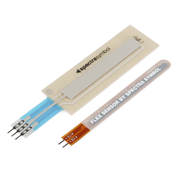
Flex Sensor and Touch Sensor

The last exercise that I did too a touch sensor and attached it to an LED. Nothing too novel there, but it's still neat to see a new kind of sensor at work. Basically the touch sensor offers a different amount of resistance depending on what point you touch, and so by touching different parts, I was able to alter the color of a three color LED.

Below is an awesome video I compiled of these three projects... with the most awesome music ever. 


I'm fast approaching the end of my Arduino workbook, but there are still a few neat components to go! 


Wednesday, January 16, 2013

Day 8: Getting Data, Creating a Thermostat

The key component of circuit 7 was using the serial connection between the Arduino and the computer. This allows the board to send output from a sensor to your computer so that you can output it onto your screen. In this case, I was given a temperature sensor and it was pretty neat to see the temperature scrolling up my screen second by second. I could blow on the sensor and see the temperature go up for a second and then float back down. 

The Sparkfun Inventor's Kit guide recommended that I make a thermostat with my temperature sensor, a potentiometer, and an LED, and so I did. The thermostat reads in a temperature that I set using a knob, compares that temperature with the temperature that it senses through a temperature sensor, and then sends a signal to turn on an LED if the temperature is below a certain level.


Ok, so it isn't exactly a thermostat. It doesn't actually control an air conditioner or a heater. Still, it's pretty close, and I wouldn't have had any idea how to do this two weeks ago. I have to say that, one of the remarkable things about playing with the Arduino is that you get a sense of how the electronics in your daily life work, and then you can just create your own mini-version that does whatever crazy thing you want it to do! Amazing!


Saturday, January 12, 2013

Day 7: Photoresistors and Mapping Functions

There's nothing new in terms of setting up this circuit. You simply create one circuit with an LED and another circuit with a photoresistor that you use as a light sensor. The photoresistor is set up in a voltage divider in the same way as the potentiometer in Day 2. It's neat to see that you can use a single setup like a voltage divider for a range of different sensors.
Voltage Divider
Even though this is fundamentally identical to the potentiometer circuit, it feels a lot cooler. You can get the LED to increase and decrease in brightness just by waving your hand in front of it. Here's a terrible video by me of the circuit in action.

The other awesomely useful thing that I learned building this circuit was the map function. In short, this easily solves the problem that I faced in my potentiometer controlled multicolored LED side project in Day 3. In that one, the potentiometer read in an analog signal between 1-1023 and the LED pins read between 0 and 255 and so I had to invent an adjustment factor to move between the two. The map function does that for me. So in this case I could do the function

lightLevel=map(lightLevel, 0, 1023, 0, 255);

which is exactly the same map function as required in this circuit as well. Cool stuff that will definitely save me time in the future!

Friday, January 11, 2013

Day 6: Push Buttons and Pullup Resistors

The SIK kit uses circuit 5 to teach people about push buttons and logic. Two push buttons are hooked up in circuits and used as inputs. An LED is then hooked up to an output. Depending on how whether you are pushing one button or two buttons, the LED will either be on or off. There are various little functions included in the included code that provide some good examples.

A Circuit with a Pullup Resistor


One of the things that really confused me, though, was the use of 10kohm resistor with the push button. The circuit looked like this:

5V -- 10,000ohm resistor -- input pin -- push button --GND

It turns out that this is pretty simple. When the push button is closed, you get the circuit:

input pin -- push button -- GND

Which sends no power to the input pin. This is a LOW signal.

When the push button is open you get the circuit

5V -- 10,000ohm resistor -- input pin

And so you are sending power to the input pin. This is a HIGH signal.

So now you can use these values of LOW and HIGH to program button behaviors. Here is a much more thorough explanation on the Sparkfun website. Awesome!

Wednesday, January 9, 2013

Day 5: Analog Write and Pulse Width Modulation (~)

Circuit #4 in the Sparkfun Inventor's Kit isn't anything too exciting in terms of introducing you to new stuff. It basically teaches you how to create a circuit with eight LEDs which you can program to turn on and off in various patterns. 

Like I said, there is almost nothing new introduced in this project, and yet, it brings a lot of things together. In fact, this is probably the first circuit that really gave me a view into a small fraction of the things that the Arduino is capable of. You see, even with just eight LEDs, you can make them light up one after another, light up all at once, or light up completely randomly. The program provided with the circuit provides a nice array of functions that allow you to generate some fun patterns with the LEDs. It's a great exercise, and a great opportunity to play around with programming a simple circuit like this one to create some fun results.

I decided that for my own project related to circuit 4, I would replace the digitalWrite function that is used in all of the various patterns with the analogWrite function. This means that instead of having the lights simply turn on and off in succession, the lights would pulse on and off slowly. I thought it would be simple enough. Basically, I took the for loops that had the lights turn on and off in succession, and added another for loop within it to gradually raise the brightness of the LED. See code below.

void glowOneAfterAnother()
{
  int index;
  int x;
  int delayTime = 10; // milliseconds to pause between LEDs

  for(index = 0; index <= 5; index++) // this loop goes through each LED
  {
    for(x=0; x <=255; x++) //this loop gradually raises the level of analogWrite from 0 to 255
    {
      analogWrite(ledPins[index], x);
      delay(delayTime);
    }      
  }

You may notice that I mentioned 8 LEDs before, but only 6 are mentioned in this code. This is due to a small hitch I encountered along the way.

When I first ran my program with the original 8 LEDs, I encountered the strange situation where about half of my LEDs gradually turned on as expected, and the other half simply turned on as if I had used digitalWrite. After double checking my code and double checking all my circuit connections, I was left scratching my head. After staring at my board for a while, I realized that all of the pins that were working as expected were plugged into digital pins with a tilde(~) next to the pin number. Apparently, only these pins are capable of what is called Pulse Width Modulation. While I don't know the exact details, pulse width modulation is basically the rapid flickering on and off of the pin that allows for the simulation of analog output required to use analogWrite. Apparently this is also useful for doing things like controlling the speed of motors. 

In the end, to get the circuit to work properly, I had to restrict the pins I used to the ones with a ~ beside them. Unfortunately there were only 6 so I had to remove two of my LEDs.

So that was my adventure with analogWrite. I'm glad it gave me the chance to understand the Arduino a little better. Now I can sit and bask in the glory of my 6 gently pulsing LED lights.

Saturday, January 5, 2013

Day 4: A Guide to Resistors

Well, I'm not feeling that well today so I figure I'll work on more theoretical stuff so that I can stay in bed. One of the things that has mystified me since I started these Arduino projects is the role of the resistor. I remember using these things when I was setting up circuits in physics class in high school, but I realized that I have no idea when or how to use what resistor. I thought I would do a little research to refresh my understanding of resistors and get a better understanding of how to use them with the Arduino.


The basic question I want to answer is the following: Why do I need a 330ohm resistor in my circuit when I attach an LED to an Arduino pin. I've been doing it since my very first circuit, but I have no idea why. Looking at various message boards proved useful. The first thing that I encountered as I looked for solutions to this question was the following equation:

V=IR where V is voltage, I is current (in amps), and R is resistance (in ohms).

This equation was sitting somewhere in the dim recesses of my memory, but I had no idea how to apply it to this situation. The next clue came when reading the specifications of an Arduino pin.

A digital Arduino pin, when set to output "High" outputs 5V. The pin is also rated at 40mA. This means that if I try to draw more than 40mA of current from any given pin on the Arduino, I might damage it. Plugging these two values into the equation above I get:

5V/0.04A=125ohm

This gives me the resistance of the resistor I need in an circuit (which plugs the pin directly into ground) with 5V to draw a current of 40mA. Playing with this relationship a bit, we can see that

5V/10ohm=0.5A of 5V/1000ohm=0.005A or 5mA

So then having a circuit with anything less than a 125ohm resistor would damage the Arduino pin. (There is likely some variance here due to the resistance in the wires themselves, so we could probably attach a resistor somewhat less than 125ohm.)

Now if we look at the LED that comes with the SIK, it says that there is a 1.8-2.2 voltage drop across the LED. Taking the median value of 2V, we can see that we now end up with:

(5V-2V)/0.04A=75ohm

So we have the value of the resistor necessary to keep from damaging the Arduino pin (75ohm). But now looking at the specification for the LED, it also says "Suggested Using Current 16-18mA." This means that, with a 75ohm resistor, we might not damage the Arduino pin, but we would damage the LED. To get the right amount of current to the LED we must recalculate:

(5V-2V)/0.017A=176.47ohm

In the kit, I have been using a 330ohm resistor which means:

(5V-2V)/330ohm=0.009 or 9mA

Judging from this, my LED is probably a little dimmer than it could be.

In writing this I found the first reply by lefty in this Arduino Forum to be extremely valuable. I also opened up a thread in the Arduino basic electronics forum where several people were extremely helpful. More on resistors later.


Wednesday, January 2, 2013

Day 3: Multicolored LEDs and a cool side project

The circuit involved in circuit three of the Sparkfun Inventor's Kit (SIK) was extremely simple. It basically involved plugging three LEDs of different colors (all in one convenient package pictured below) into a circuit.


The really cool bits were in the programming where I was introduced to two new concepts. First was the function analogWrite(PIN, Intensity) which basically simulates analog output. The SIK guide has a nice explanation of the function, but basically what it does is flickers a digital output on and off at various speeds to approximate analog output. The result in the case of the LED was changing intensities of the LEDs based on the values in the intensity level put into the analogWrite function.

The other important concept was the use of a for loop in programming the Arduino. I've encountered loops many times in the past doing other types of programming but this is the first time I've encountered it in this setting. Unsurprisingly, they worked in exactly the same way. The function that was created basically cycled the three color LED through the color spectrum by varying the brightness of the three LEDs. Since the analogWrite function takes intensities between 0 and 255, it was simply a matter of creating a new function (called showSpectrum) that looped through values of 0 and 255 on each of the three colors. The code looked like this:


void showSpectrum()
{
  int x;  // define an integer variable called "x"
  
  // Now we'll use a for() loop to make x count from 0 to 767
  // (Note that there's no semicolon after this line!
  // That's because the for() loop will repeat the next
  // "statement", which in this case is everything within
  // the following brackets {} )

  for (x = 0; x < 768; x++)

  // Each time we loop (with a new value of x), do the following:

  {
    showRGB(x);  // Call RGBspectrum() with our new x
    delay(10);   // Delay for 10 ms (1/100th of a second)
  }
}


// showRGB()

// This function translates a number between 0 and 767 into a
// specific color on the RGB LED. If you have this number count
// through the whole range (0 to 767), the LED will smoothly
// change color through the entire spectrum.

// The "base" numbers are:
// 0   = pure red
// 255 = pure green
// 511 = pure blue
// 767 = pure red (again)

// Numbers between the above colors will create blends. For
// example, 640 is midway between 512 (pure blue) and 767
// (pure red). It will give you a 50/50 mix of blue and red,
// resulting in purple.

// If you count up from 0 to 767 and pass that number to this
// function, the LED will smoothly fade between all the colors.
// (Because it starts and ends on pure red, you can start over
// at 0 without any break in the spectrum).


void showRGB(int color)
{
  int redIntensity;
  int greenIntensity;
  int blueIntensity;

  // Here we'll use an "if / else" statement to determine which
  // of the three (R,G,B) zones x falls into. Each of these zones
  // spans 255 because analogWrite() wants a number from 0 to 255.

  // In each of these zones, we'll calculate the brightness
  // for each of the red, green, and blue LEDs within the RGB LED.

  if (color <= 255)          // zone 1
  {
    redIntensity = 255 - color;    // red goes from on to off
    greenIntensity = color;        // green goes from off to on
    blueIntensity = 0;             // blue is always off
  }
  else if (color <= 511)     // zone 2
  {
    redIntensity = 0;                     // red is always off
    greenIntensity = 255 - (color - 256); // green on to off
    blueIntensity = (color - 256);        // blue off to on
  }
  else // color >= 512       // zone 3
  {
    redIntensity = (color - 512);         // red off to on
    greenIntensity = 0;                   // green is always off
    blueIntensity = 255 - (color - 512);  // blue on to off
  }

  // Now that the brightness values have been set, command the LED
  // to those values

  analogWrite(RED_PIN, redIntensity);
  analogWrite(BLUE_PIN, blueIntensity);
  analogWrite(GREEN_PIN, greenIntensity);
}

I've left the comments in so that everything is clear. Not too terribly complicated.

And finally for the good stuff. After finishing exercise 3, I thought to myself, wouldn't it be fun if I could make the LEDs cycle through the spectrum based on twisting the potentiometer? Thus my very first independent arduino project was born. Here is my needlessly dramatic video of the results.


In the end the project basically involved making a circuit that was a hybrid of the potentiometer circuit created in circuit 2 with the circuit I had just created. I created one circuit which plugged the potentiometer into the analog input of the arduino and left the three color LED just the way it was in circuit 3.

The programming was slightly trickier and I've uploaded it to scribd here. Most of the code is pretty easy if you understand circuit three. The only tricky part is to realize that the output from the potentiometer ranges from 1-1023 while the function we've created to cycle through the color spectrum goes from 1-766. As a result, we need to map the values 1-1023 to 1-766 and this is done by multiplying the output from the potentiometer by a factor 766/1023.

And there you have it! A cute little side project!