Showing posts with label Sparkfun. Show all posts

Monday, January 21, 2013

Day 9: Servos and Sensors

Wow! Servos! Not only do they sound incredibly cool, but they also open up a whole range of possibilities. You see, unlike a regular motor which just spins, servos allow you to precisely control how many degrees you want to turn them. So, for example, you can connect them to a sensor and have that sensor determine how much something turns. As a proof of concept, I tried connecting a servo up to a potentiometer. Basically, by turning a dial, I controlled how far the servo turned. Nothing too exciting. 


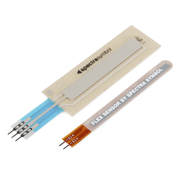
The next exercise actually had me attach a flex sensor to the servo so that by bending a little strip, I could control how far the servo turns. This, unlike my previous little exercise, really triggers my imagination. Imagine, you could stick a set of these sensors inside a glove and have them control the motion of a robotic hand. By adjusting the strength of the servo, you could translate your motion into a robotic grip of death.

Flex Sensor and Touch Sensor

The last exercise that I did too a touch sensor and attached it to an LED. Nothing too novel there, but it's still neat to see a new kind of sensor at work. Basically the touch sensor offers a different amount of resistance depending on what point you touch, and so by touching different parts, I was able to alter the color of a three color LED.

Below is an awesome video I compiled of these three projects... with the most awesome music ever. 


I'm fast approaching the end of my Arduino workbook, but there are still a few neat components to go! 

Wednesday, January 16, 2013

Day 8: Getting Data, Creating a Thermostat

The key component of circuit 7 was using the serial connection between the Arduino and the computer. This allows the board to send output from a sensor to your computer so that you can output it onto your screen. In this case, I was given a temperature sensor and it was pretty neat to see the temperature scrolling up my screen second by second. I could blow on the sensor and see the temperature go up for a second and then float back down. 

The Sparkfun Inventor's Kit guide recommended that I make a thermostat with my temperature sensor, a potentiometer, and an LED, and so I did. The thermostat reads in a temperature that I set using a knob, compares that temperature with the temperature that it senses through a temperature sensor, and then sends a signal to turn on an LED if the temperature is below a certain level.


Ok, so it isn't exactly a thermostat. It doesn't actually control an air conditioner or a heater. Still, it's pretty close, and I wouldn't have had any idea how to do this two weeks ago. I have to say that, one of the remarkable things about playing with the Arduino is that you get a sense of how the electronics in your daily life work, and then you can just create your own mini-version that does whatever crazy thing you want it to do! Amazing!


Friday, January 11, 2013

Day 6: Push Buttons and Pullup Resistors

The SIK kit uses circuit 5 to teach people about push buttons and logic. Two push buttons are hooked up in circuits and used as inputs. An LED is then hooked up to an output. Depending on how whether you are pushing one button or two buttons, the LED will either be on or off. There are various little functions included in the included code that provide some good examples.

A Circuit with a Pullup Resistor


One of the things that really confused me, though, was the use of 10kohm resistor with the push button. The circuit looked like this:

5V -- 10,000ohm resistor -- input pin -- push button --GND

It turns out that this is pretty simple. When the push button is closed, you get the circuit:

input pin -- push button -- GND

Which sends no power to the input pin. This is a LOW signal.

When the push button is open you get the circuit

5V -- 10,000ohm resistor -- input pin

And so you are sending power to the input pin. This is a HIGH signal.

So now you can use these values of LOW and HIGH to program button behaviors. Here is a much more thorough explanation on the Sparkfun website. Awesome!

Wednesday, January 2, 2013

Day 3: Multicolored LEDs and a cool side project

The circuit involved in circuit three of the Sparkfun Inventor's Kit (SIK) was extremely simple. It basically involved plugging three LEDs of different colors (all in one convenient package pictured below) into a circuit.


The really cool bits were in the programming where I was introduced to two new concepts. First was the function analogWrite(PIN, Intensity) which basically simulates analog output. The SIK guide has a nice explanation of the function, but basically what it does is flickers a digital output on and off at various speeds to approximate analog output. The result in the case of the LED was changing intensities of the LEDs based on the values in the intensity level put into the analogWrite function.

The other important concept was the use of a for loop in programming the Arduino. I've encountered loops many times in the past doing other types of programming but this is the first time I've encountered it in this setting. Unsurprisingly, they worked in exactly the same way. The function that was created basically cycled the three color LED through the color spectrum by varying the brightness of the three LEDs. Since the analogWrite function takes intensities between 0 and 255, it was simply a matter of creating a new function (called showSpectrum) that looped through values of 0 and 255 on each of the three colors. The code looked like this:


void showSpectrum()
{
  int x;  // define an integer variable called "x"
  
  // Now we'll use a for() loop to make x count from 0 to 767
  // (Note that there's no semicolon after this line!
  // That's because the for() loop will repeat the next
  // "statement", which in this case is everything within
  // the following brackets {} )

  for (x = 0; x < 768; x++)

  // Each time we loop (with a new value of x), do the following:

  {
    showRGB(x);  // Call RGBspectrum() with our new x
    delay(10);   // Delay for 10 ms (1/100th of a second)
  }
}


// showRGB()

// This function translates a number between 0 and 767 into a
// specific color on the RGB LED. If you have this number count
// through the whole range (0 to 767), the LED will smoothly
// change color through the entire spectrum.

// The "base" numbers are:
// 0   = pure red
// 255 = pure green
// 511 = pure blue
// 767 = pure red (again)

// Numbers between the above colors will create blends. For
// example, 640 is midway between 512 (pure blue) and 767
// (pure red). It will give you a 50/50 mix of blue and red,
// resulting in purple.

// If you count up from 0 to 767 and pass that number to this
// function, the LED will smoothly fade between all the colors.
// (Because it starts and ends on pure red, you can start over
// at 0 without any break in the spectrum).


void showRGB(int color)
{
  int redIntensity;
  int greenIntensity;
  int blueIntensity;

  // Here we'll use an "if / else" statement to determine which
  // of the three (R,G,B) zones x falls into. Each of these zones
  // spans 255 because analogWrite() wants a number from 0 to 255.

  // In each of these zones, we'll calculate the brightness
  // for each of the red, green, and blue LEDs within the RGB LED.

  if (color <= 255)          // zone 1
  {
    redIntensity = 255 - color;    // red goes from on to off
    greenIntensity = color;        // green goes from off to on
    blueIntensity = 0;             // blue is always off
  }
  else if (color <= 511)     // zone 2
  {
    redIntensity = 0;                     // red is always off
    greenIntensity = 255 - (color - 256); // green on to off
    blueIntensity = (color - 256);        // blue off to on
  }
  else // color >= 512       // zone 3
  {
    redIntensity = (color - 512);         // red off to on
    greenIntensity = 0;                   // green is always off
    blueIntensity = 255 - (color - 512);  // blue on to off
  }

  // Now that the brightness values have been set, command the LED
  // to those values

  analogWrite(RED_PIN, redIntensity);
  analogWrite(BLUE_PIN, blueIntensity);
  analogWrite(GREEN_PIN, greenIntensity);
}

I've left the comments in so that everything is clear. Not too terribly complicated.

And finally for the good stuff. After finishing exercise 3, I thought to myself, wouldn't it be fun if I could make the LEDs cycle through the spectrum based on twisting the potentiometer? Thus my very first independent arduino project was born. Here is my needlessly dramatic video of the results.


In the end the project basically involved making a circuit that was a hybrid of the potentiometer circuit created in circuit 2 with the circuit I had just created. I created one circuit which plugged the potentiometer into the analog input of the arduino and left the three color LED just the way it was in circuit 3.

The programming was slightly trickier and I've uploaded it to scribd here. Most of the code is pretty easy if you understand circuit three. The only tricky part is to realize that the output from the potentiometer ranges from 1-1023 while the function we've created to cycle through the color spectrum goes from 1-766. As a result, we need to map the values 1-1023 to 1-766 and this is done by multiplying the output from the potentiometer by a factor 766/1023.

And there you have it! A cute little side project!


Friday, December 28, 2012

Day 2: Getting to know the Potentiometer

I think the last time I actually built any kind of circuit was in my freshman year physics class in college (8 years ago). Unsurprisingly I've forgotten almost everything. Today as I started circuit number 2 in my SparkFun Inventor's Kit I was faced with a component called a potentiometer (or variable resistor).


This little fella here basically has three pins and a little knob on the top that you can rotate and is described in the SparkFun guide as a knob that can raise and lower resistance, like a dimmer switch or a volume knob. The two outer pins connect to the power and the ground, and the central pin which is the output. It seems that in general, the way that these things work is that a connection is made between some sort of resistive material (apparently graphite in cheap potentiometers) organized in an arc and the power. By turning the knob on the potentiometer, you adjust the amount of resistive material between the power and the output by moving the second contact to a position further on the arc. This site explains it far more clearly than me. It's a surprisingly simple and elegant design... and I always thought that the inner workings of any of these things would be impossible to understand!

The second project in the kit involves setting up the potentiometer so that it can adjust the speed of the blinking of an LED, and getting this to work was surprisingly simple. Basically I made two circuits. One of the circuits is between the arduino and the LED, and the other is between the arduino and the potentiometer.


It's at this point that the manual discusses some crucial aspects of the arduino board: analog and digital pins. Basically, the analog pins take a value between 0 and 5 volts and translates them into a number between 0 and 1023 (more on this later). The digital pin is for dealing with values of things that are either off (0 volts) or on (5 volts) like say a blinking LED.

Now the code:

int sensorPin = 0;
int ledPin = 13;

void setup()
{
pinMode(ledPin, OUTPUT);
}

void loop()
{
int sensorValue;
sensorValue = analogRead(sensorPin);
digitalWrite(ledPin, HIGH);
delay(sensorValue);
digitalWrite(ledPin, LOW);
delay(sensorValue);
}

If you are unfamiliar with Arduino code, this might look complicated but it's actually pretty straightforward, especially if you know some programming. Here are the key lines:


sensorValue = analogRead(sensorPin);
This reads the value from the potentiometer and sets it to a variable called sensorValue

digitalWrite(ledPin, HIGH); This turns on the LED
delay(sensorValue);  This keeps the next line from running for sensorValue milliseconds 
digitalWrite(ledPin, LOW); This turns off the LED
delay(sensorValue);

That's it. Just read in the value of the potentiometer and turn the light on and off delaying by the returned value from the potentiometer. It's really surprising to me that such a simple set of code could get this done. I was expecting it to be much more complicated, but perhaps that is why arduino is so popular.

Thursday, December 27, 2012

Day 1: Opening the Sparkfun Inventor's Kit

My wife, Victoria, was kind enough to purchase the Sparkfun Inventor's Kit for me for Christmas. This kit costs about $95 and includes an Arduino board for running programs, a breadboard for creating circuits, and a variety of things like motors, sensors, and LEDs to hook up in a circuit. It also comes with a very nice manual with some basic projects. The code for the projects which can be uploaded to the Arduino are available online.

It's a nice kit that comes with a nice plastic box to keep everything in. Fancy eh?


Everything in the box comes in nice little labelled pouches. All you have to do is attach the Arduino and the breadboard to the little plastic dish they give you. Below are the contents of the package.


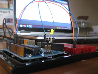
Setting up the Arduino with my computer could not have been easier. Just follow some simple instructions on the Arduino website. I was up and running my first program in about 10 minutes. Since the Arduino was powered by the USB port connected to my PC, there was no need to hook up batteries or anything. Once all the drivers were installed, I followed some of the simple instructions for the first circuit presented in the Sparkfun manual. It's a simple circuit that creates a blinking LED light.

As you can see, the instructions are accompanied by very clear and helpful illustrations and explanations. After setting up the circuit, I opened up the provided code which was also very clearly annotated. I hit upload and boom! Blinking LED!
By adjusting the program a little bit, I was able to adjust the speed of the blinking. Simple but fun. Who knew a simple little blinking light could bring so much joy! And thus ended my first day of playing with my new Arduino.